verilog_FSM
This is a basic project about FSM
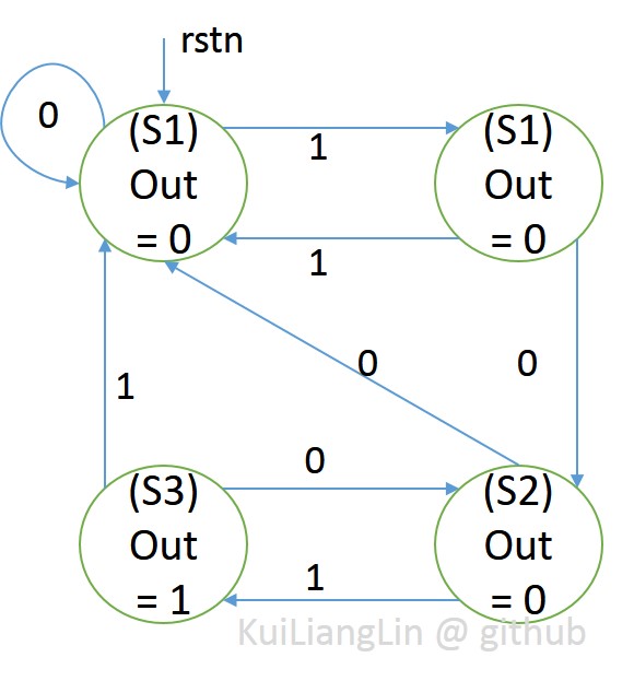
if input sequence = 101, output = 1; else output = 0;
Basic Mealy FSM structure :
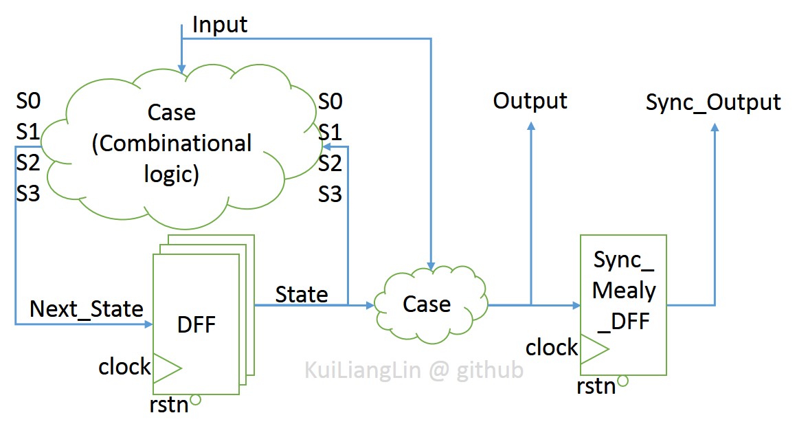
According to Mealy FSM structure , we get Mealy FSM sequence :
Basic Moore FSM structure :
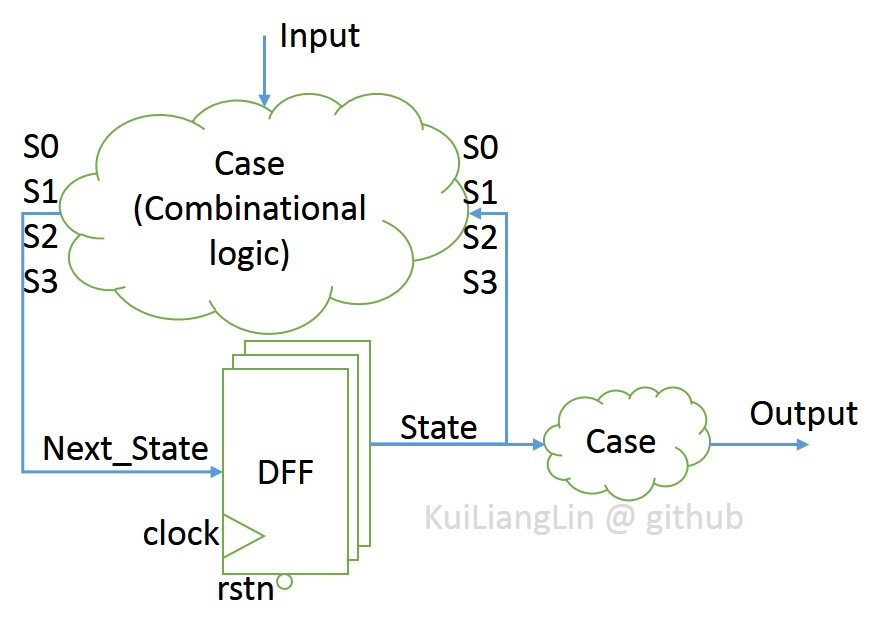
According to Moore FSM structure , we get Moore FSM sequence :
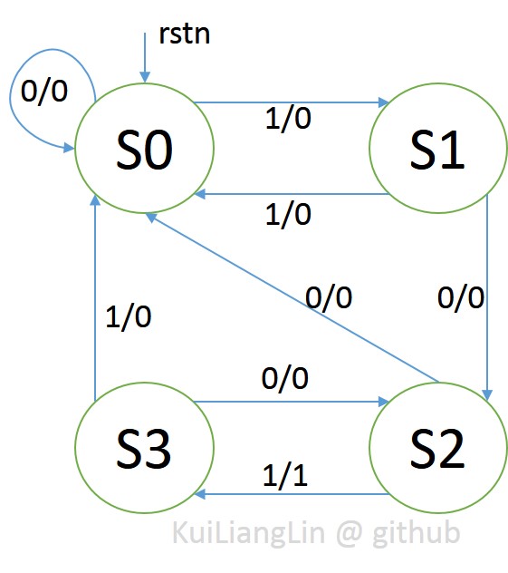
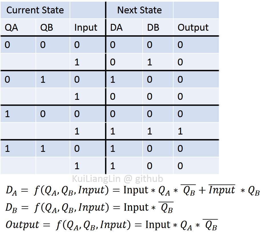
According to the FSM sequence, we get truth table.
Because each bit of state is represented by a register, we know DA, DB, and output are fuction of QA, QB, and input.
Thus we use K-map to simplify them.
After simplified by K-map, we get gate level circuit.
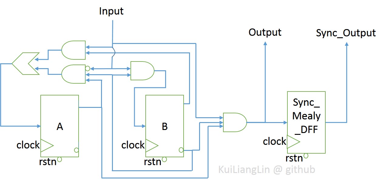
Test bench is used to see the comparision of output among Moore, Mealy, and equivalent gate level circuit.
Conclusion :
-
number of moor state = number of mealy state * number of output +1
-
Moore Machines are safer to use :
- Outputs change at clock edge (always one cycle later)
-
In Mealy machines, input change can cause output change as soon as logic is done -
- asynchronous feedback could cause a big problem when two machines are interconnected
-
Mealy Machines react faster to inputs
-
React in same cycle – don’t need to wait for clock
-
output is affected by noise of input
-
-
In Moore machines, more logic may be necessary to decode state into outputs
- more gate delays
-
small fsm -> binary, gray code; big fsm -> one hot
- one hot uses more register, but low dynamic power consumption
(only two bits are changed while state changes)
END
- Codes are Here.
- You can return My Main Page.